Dear Readers,
I have been getting questions about my article from 2018 on why you can’t use an adapter on a 240-volt welding outlet to power an RV. I’ll post that article later.
Here’s one question that was posed…
Mike, thanks for the article. Very helpful.
And there is another detail in the circuit that confuses me. The RV 50A twist locks only have three pins, while the other end (NEMA 14-50) has 4 pins (Ground, 110 Hot, 110 Hot, neutral). Where is the safety ground conductor on the twist lock 50A connection? Is it the little metal plate on the outside? Where is the neutral? Do you have a diagram of that connector? —Marcus
Some visuals, please…
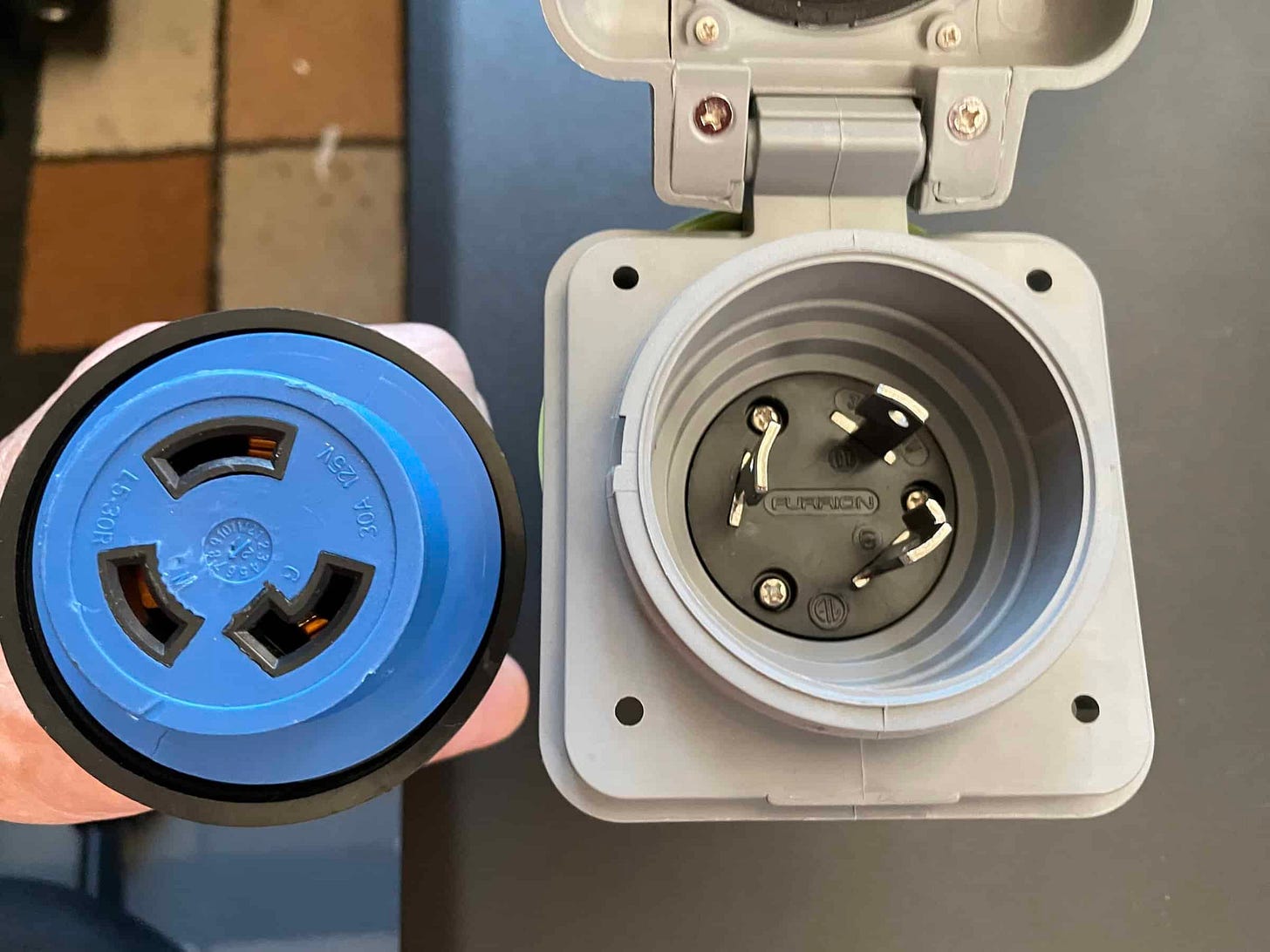
And here’s the source of confusion. This is what a 30-amp, 3-wire (Hot, Neutral, Ground) shore power connection looks like.
It should be obvious from the picture that there are three separate curved contacts in the plug and inlet. So those are what’s connected to the pedestal’s TT-30 outlet’s Hot, Neutral and Ground conductors. Easy, peasy….
But what about a 50-amp twist-lock connector?
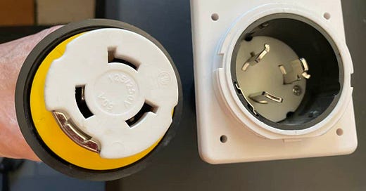
Here’s where it gets a bit confusing. If you look at the 50-amp shore power inlet and plug you’ll see the same three curved contacts.
But what may not be so obvious is the extra sliding contact on the side of the plug and inlet housing. That’s what creates the ground connection.
To review, a 50-amp RV shore power service with 120/240 volts has Hot-1, Hot-2, Neutral and Ground conductors. However, a welder outlet is 240 volts only, so it only has Hot-1, Hot-2 and Ground conductors, with no Neutral conductor. That’s why it won’t work to power an RV.
Hooking it up
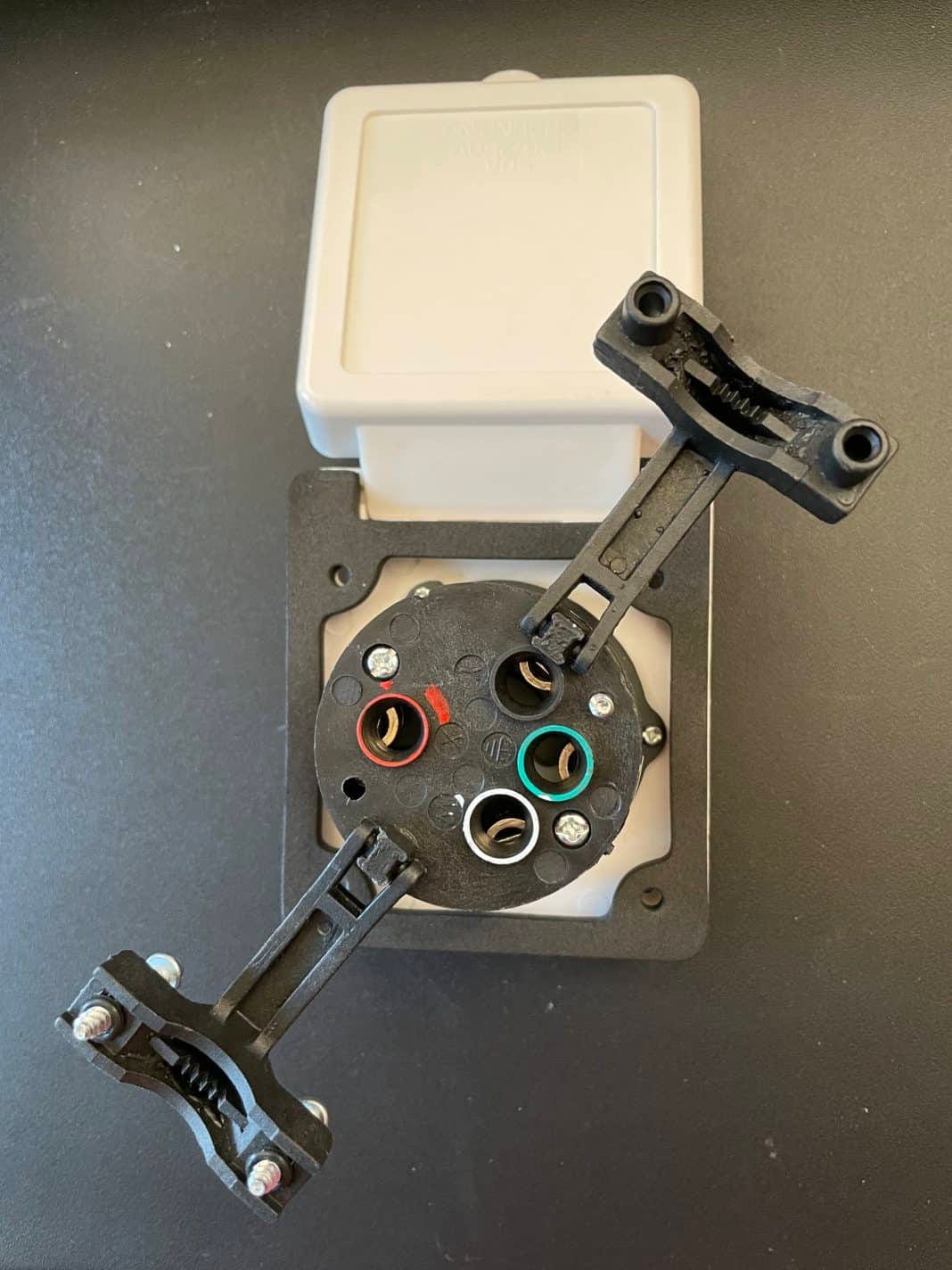
And here’s what the back of the 50-amp twist-lock inlet looks like. As you can see, there’s color coding on each of the terminating screws.
So the Black hole is Hot-1, the Red hole is Hot-2, the White hole is Neutral and the Green hole is Ground. So you just need to match up the colors of the conductors.
Plus, as I’ve noted before, the Ground and Neutral conductors must remain isolated from each other inside of the RV. They are only bonded together from the shore power service panel, generator, and many times the inverter.
So there’s no green bonding screw inside of the RV’s power panel. And there’s no bonding screw inside of the pedestal, either. There can only be one bonding point. When you’re plugged into shore power, that’s located at the campground or residential incoming service panel.
Hope this helps explain how it works.
Let’s play safe out there… Mike.


Thank you for the detailed explanation and the high resolution photos. I have found it also helps to look closely at the molded in letters on the face of the connectors - L5-30R 30 amp 125V and 50 amp 125/250V.
Thanks for the information. I enjoy reading you articles on RV electricity.