Finding 12-Volt DC Short Circuits! Part 2
How to find a short circuit without blowing a bunch of fuses….
Dear Readers,
As promised, here’s Part 2 of my 12-volt DC short circuit tutorial. If you haven’t read it already or just need a refresher, please review Part 1 from last week HERE.
A Quick Review
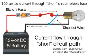
First let’s take a quick review at what a short circuit looks like in a 12-volt DC circuit. You should remember from last week that the word “short” actually means a “shorter” circuit path than intended. And because the 12-volt bulb is what provided the current limiting in the non-shorted circuit, once you have a short in the wire you’ll blow a fuse every time you plug in a new one. That gets expensive and really doesn’t reveal anything diagnosticly.
First Steps
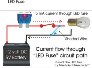
So what are we to do? Well, the simplest troubleshooting device we can add is an LED fuse which only cost about $1 each. While the fuse does indeed blow due to the huge short-circuit current available, now the LED light bulb is in the current path, and that tells us there’s at least 5 mA (5 milliamp or 0.005 amperes) of current flowing in the circuit.
Note that due to its low current requirements the LED bulb will light even if the short circuit has been removed but the bulb (or other load) is still in place. So if we want to find an intermittent short circuit with an LED fuse, the best way is to simply pop out the light bulb from the socket or removed any other load (as I’ve indicated in the diagram), then flex every wire and connector that’s in the circuit path and see if you can make the LED blink on and off. When the LED fuse is lit up you have a short circuit, and when the LED fuse is off there’s no short. So the trick is to flex, pound, twist and in general create mayhem with the wiring and see if the LED will flicker or go off.
Divide and conquer
Once you can create the intermittent short circuit at will, you simply divide and conquer the actions that will make it blink until you find the offending spot, which in many cases can be nothing more than a wire laying over a sharp metal edge that has cut through the insulation. If that’s the case, you can tape up the cut spot in the insulation and do something to keep it from being cut again. More on that in a future article.
But wait, there’s more…
However, what if you want to troubleshoot this problem while the main bulbs are still in the circuit. The fuse LED bulb draws so little current that it won’t know the difference between a short circuit and a normal circuit feeding a 12-volt light bulb load. So we have to increase the test current without creating so much fault current that it melts the wire.
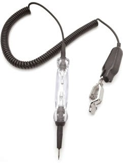
Get a 12-volt tester with a 3-watt tungsten bulb
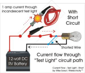
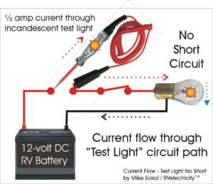
Enter the 12-volt test light with a built-in incandescent bulb. You don’t want a modern LED version of this test light because it won’t draw enough current for an in-load test. Note that in this example the test light will be drawing full current and be brightly lit, while the light bulb circuit in question has no current going through it and is off with no light at all.
They’re getting harder to find nowadays since LED bulbs have taken over, but you can still buy one on Amazon for around $20 HERE.
Going deeper…
The old-school version of the 12-volt tester is what you need since it draws more current than the modern LED models, and more current is what we need for testing like this. Note that instead of using this test light in the normal way between chassis ground and the hot terminal, you’re placing it in what used the fuse path. Now it’s doing two things. First, the bulb inside of the tester is limiting the fault current through the short circuit to less than 1 ampere or so and, second, it’s giving you a visual indication of how much current is flowing due to a short circuit.
Now, as you can see in the next graphic, depending on how much of a load you have downstream, the test light bulb may not be totally bright or dim without a short circuit since the load bulb is also limiting the current flow by its own resistance. But the test light will generally go from dim (with no short circuit) to fully bright (with a short circuit).
Just repeat the same wiggle process on the wiring while getting someone to watch the trouble light bulb for brightness changes. When the test light is fully bright and the load light is off, then the circuit is shorted. But when the test light is dim and the load light is dim, then there’s no longer a short circuit. The trick is to recognize what kind of twist, thump or wiggle causes the test light to change brightness. Then you’ve found where your short circuit is located.
One last thing…
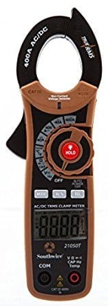
Since this is a lot to absorb in one sitting, I’m going to give you a preview of what’s going to be included in Part 3. Next week I’ll cover how to use a DC clamp ammeter to actually trace the fault current path in a complex short circuit. Note that most clamp meters only read AC current using their clamp jaws, so you’ll need one that’s rated for AC/DC current in the jaws themselves. We’ll not only use this cool tool for DC short circuit testing, we’ll also use it when we cover AC short circuit troubleshooting. See you then…
Let’s play safe out there…. Mike



Im enjoying your articles on finding short circuits Mike. Thanks for putting you great ideas out there! I really like audio feedback so I have had some success jumping in an Ohm meter with audio feedback enabled. Of course you need to isolate the circuit under test from any power sources and test it to confirm zero voltage before attaching the Ohm meter. The ear is very sensitive to changes in sound level when wiggling wires :) I’ve also found that shorts happening by themselves are relatively rare so it’s usually a good idea to check the last thing you worked on to see if the culprit is related to something you did unintentionally.
Mike, did I somehow miss part 3 of the series?