Dear Readers,
I recently realized, after trying to explain to an electrician the facts of how electricity gets from the electric pole into your RV outlets, that there were no basic diagrams to be found. So I’ve started making drawings of the entire campground power distribution layout, which I’ll publish here. While this looks complicated at first glance, it’s really pretty straightforward.
Part 1 today will cover how it’s all hooked up according to the National Electrical Code, which also shows how the neutral and ground wires are bonded (connected) together in the power company incoming service panel, but nowhere else. And Part 2 next month will cover all the various load and fault current paths, including how to integrate a generator with a floating neutral into your RV’s electrical system.
Where to begin?
Most of you have never seen a schematic diagram of what’s on the electric pole coming into the campground or your own house, so here’s where the power begins for you.
Starting at the left side of the diagram you’ll see there’s a transformer either on the pole or on a pad being fed with around 7,000 volts of electricity. Yes, those are what we call primary wires since they carry electricity from the substation to the campground’s power transformer. The reason why the voltage is up as high as 7,000 to 11,000 volts is to reduce the voltage drop over the miles of wire connecting the campground or your residence to the power company.
And indeed it starts out as much higher voltages on the big high-tension lines you see going across the fields, with 110,000-, 250,000- and 500,000-volt lines being pretty common. Again, higher voltage equates into less current for a given amount of wattage, and less current equals less voltage drop. Take my word for it now, but someday I’ll show you all how Ohm’s Law works.
Transformers
The purpose of the power company transformer is to step-down the incoming 7,000 or 11,000 volts to 240-volts. And as you can see, that 240-volt winding is also split down the middle to create a pair of 120-volt outputs (which is why it’s called split-phase). You’ll also find that the bottom of most electric poles in the USA have a ground rod/pad installed, which functions as a place for lightning strikes to find “ground.” OK so far?
This power company transformer then feeds 240/120-volt power to the campground’s incoming service panel. You have the same thing in your own house, which might be a 100- or 200-amp service. For future discussion you should know that a 100-amp service can supply 100 amperes of current at 240 volts, or 200 amperes of current at 120 volts. And a 240-volt, 200-amp service can supply 400 amperes of current at 120 volts. Many campgrounds have a 400-amp (or larger) service panel because they need to feed power to multiple pedestals.
Neutral-ground bonding
You should also see that the incoming service panel includes a Neutral-Ground bonding point, which is typically a green screw in the neutral bus bar which bonds (connects) it to the metal box and service panel grounding rod that’s installed at the campground. This is how modern electrical code works, but it’s possible to find really old installations that do some strange grounding things. More on that MUCH later.
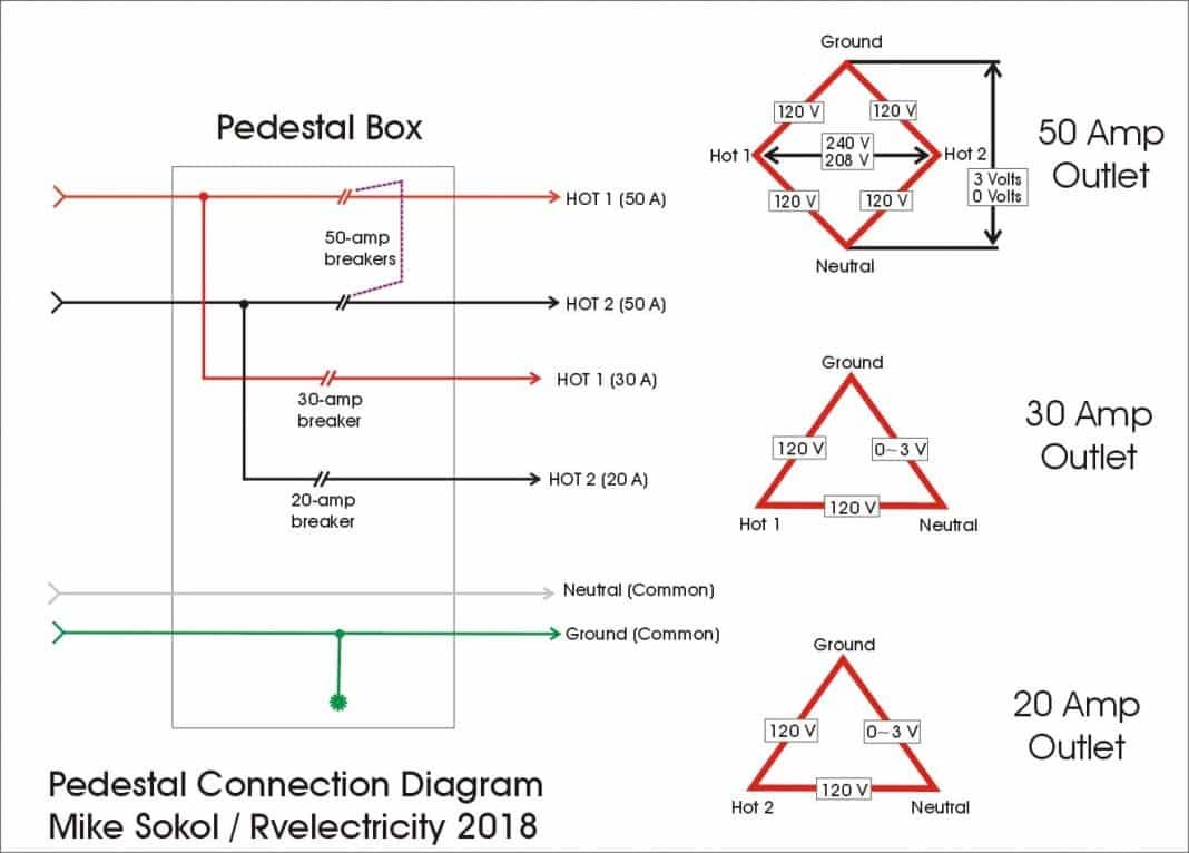
Now let’s take a look at what’s inside of a campground pedestal. You’ll see that it has incoming Hot 1, Hot 2, Neutral and Ground wires. The two Hot Legs (as they’re often called) go to several circuit breakers powering the various outlets in the pedestal panel. So there’s a double-pole 50-amp breaker feeding the 50-amp/240-volt outlet (50 amps x 2 = 100 amps at 120-volts), a single-pole 30-amp breaker feeding the 30-amp outlet, and a single-pole 20-amp breaker feeding the 20-amp outlet. Yes, the 20-amp outlet must be GFCI protected according to code, but for simplification I’m going to ignore that on this diagram.
What, no ground rods or neutral bonds?
One thing that you’ll see missing on the campground pedestal is a separate ground rod or neutral-ground bonding screw. There will be a ground wire bonding screw from the green/ground bus to the metal box, but that’s NOT connected to the incoming neutral wire.
Again, the G-N (Ground to Neutral) bonding point should only be done in the incoming service panel, and NOT the sub-panel or campground pedestal. This ground wire is technically called an EGC or Equipment Grounding Conductor, and is only allowed to carry FAULT current (when something goes wrong), and not LOAD current (which is what you draw to power your RV appliances).
Again, this G-N bonding point (as well as an earth grounding rod) is only included on the incoming service panel, NOT the campground pedestal, which is wired just like a secondary circuit breaker panel in your house.
The RV connection
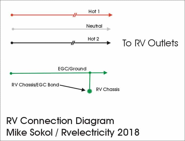
Finally, the power is fed from the outlet in the pedestal into the power distribution center of your RV, where it has its own incoming 20-, 30- or 50-amp circuit breaker, and outgoing 15- and 20-amp breakers to feed your air conditioner, 12-volt converter, microwave, etc.
I’ve simplified this diagram without the output breakers to show that there’s definitely NO Neutral-Ground bonding screw in this box, but there IS an EGC (Equipment Grounding Conductor) connected to an RV chassis bonding point. This connection is what eliminates any hot-skin/stray-voltage on your RV chassis (and skin) in the event of a fault current caused by normal internal appliance leakage, or even something like a metal screw poked through a wire accidentally. (Hey, stuff happens.)
Time to power down…
Wow, I think that’s enough for now. As you can see, there’s a very specific order as to how all of this hooks up, and there can only be ONE Ground-Neutral bonding point at the campground’s incoming service panel. And there are no ground rods at your RV or the pedestal.
So what’s all this mysterious naming of Grounds, Ground-planes, Earth Grounds, Ground Rods, Equipment Grounding Conductors, and Neutral-Ground Bonds? Yes, they’re all different things and have different functions. But if you’re going to wire ANYTHING connected to 120 volts, then you need to know the difference. So stay tuned tor more info on RV and campground grounding soon.
In the meantime, let’s play safe out there (especially around electricity)… Mike


Sometimes some of this stuff flies over my head, but I read it anyway. And this is why I pay electricians to work on my house . . .
Thanks for this detail Mike - very useful information.
But of course - it leads lo further questions. Such as -
if there are no individual CG pedestal grounding rods, but theoretically just 1 grounding rod at the CG main panel, then it would seem that a lightening strike on any pedestal (or RV) anywhere in the park would travel to all RVs on the same main pedestal circuit. Correct?
Given that all RVs in any park are very exposed to lightening I would have expected that pedestal grounding would be a requirement in order to better isolate lightening high voltage. Or at least require a series of pole mounted lightening rods all around the park to better lightening away from the RV's there.